
Our 2018 Lexor came with a battery separator for charging the house batteries (LiFePO4) from the alternator while driving. Newer Lexors incorporate a DC to DC charger instead. We decided it was time to upgrade our system.

Results
Alternator -> Fuse box positive bus -> Circuit Breaker -> DC to DC Charger -> Circuit Breaker -> Blue Sea On/Off Switch –> House Battery


Parts
Choosing a Charger
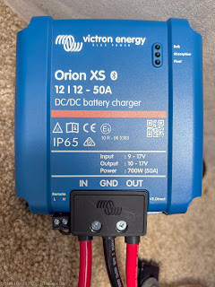
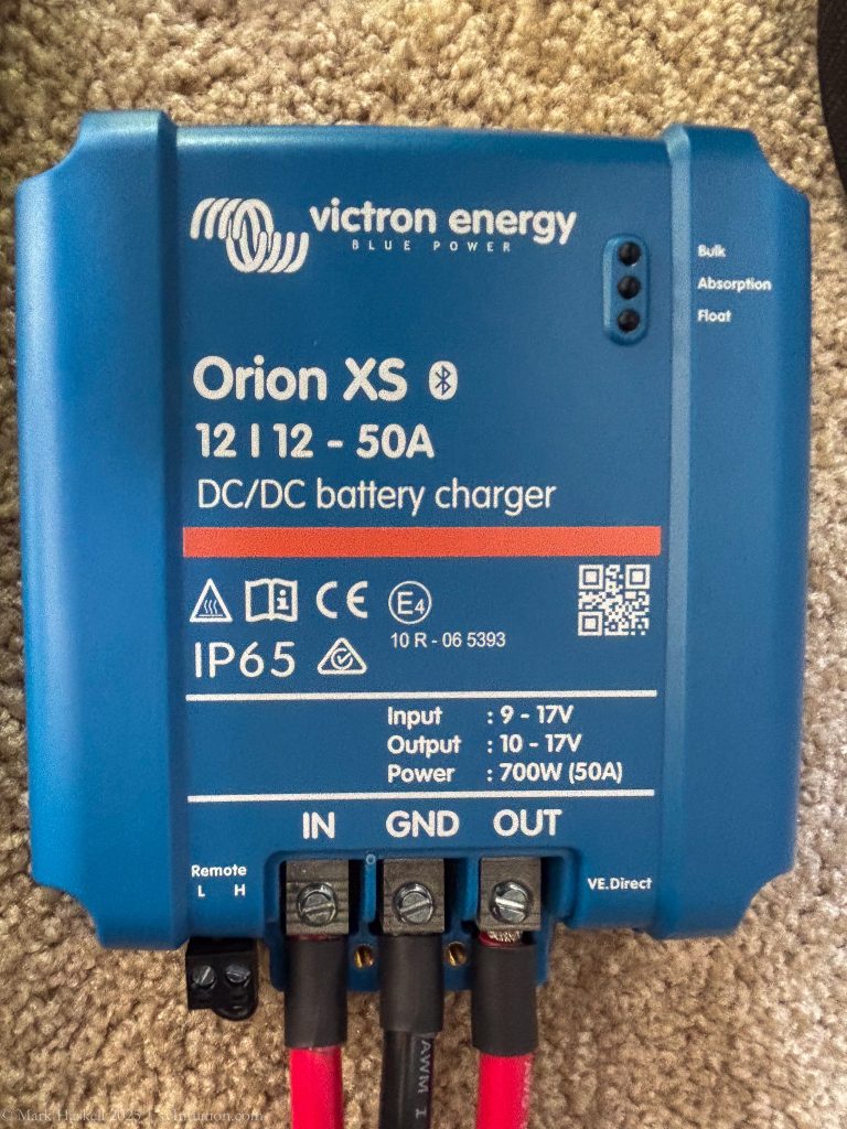
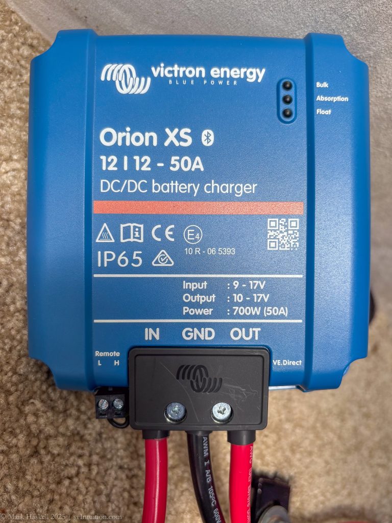
Pleasure-Way uses a Mastervolt 12 Volt 50 Amp DC to DC charger and we ordered one from West Marine. Upon receiving it we looked at the size vs the space available and decided to see if there were other options. Victron recently released a model with similar specifications that was less expensive and smaller. It also sends real-time charging information to a cellphone app, a capability that the Mastervolt does not have. After reading a few reviews, we returned the Mastervolt and bought a Victron Orion XS 12 | 12 – 50A DC to DC battery charger.
Installing the Charger
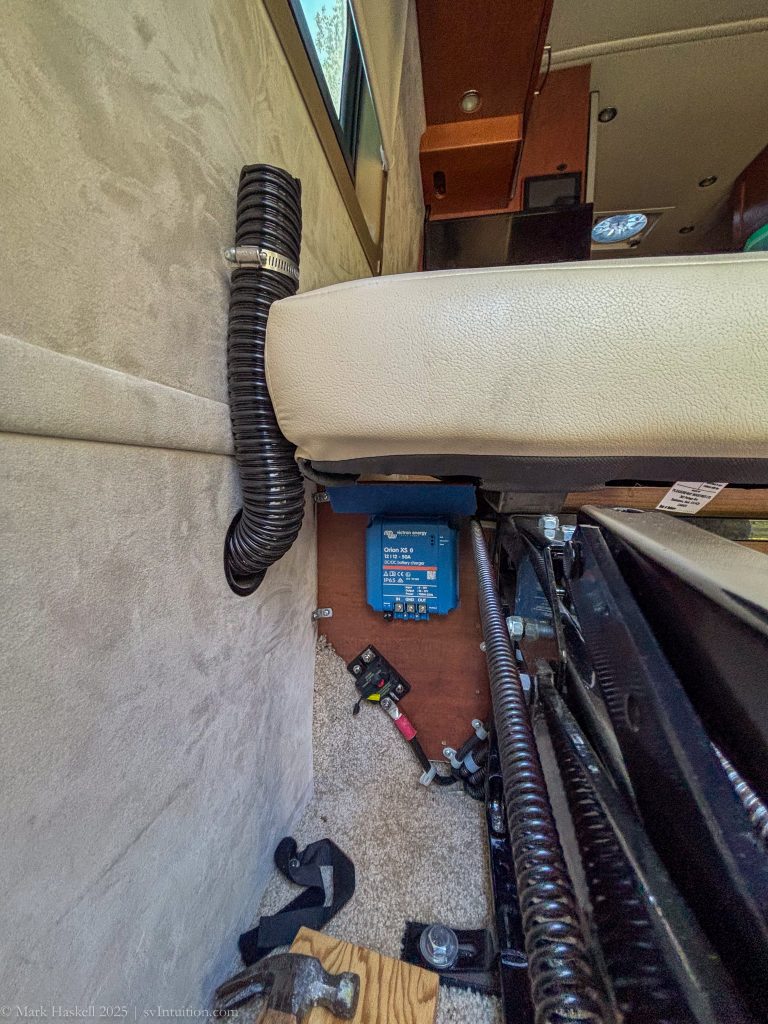
We decided to install the charger in the back of the van, rather than under the hood where the Battery Separator lived. To test that the charger would fit and function properly, we initially left the wiring under the hood alone.
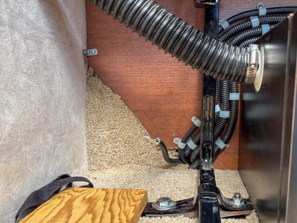
Two long wires carry the current from the battery separator to the “red key” switch under the couch in the back of the van. These emerge from the back of the driver’s side ottoman. The plan was to cut one of these wires and install the new charger between where the wire emerges and the “red key” switch.
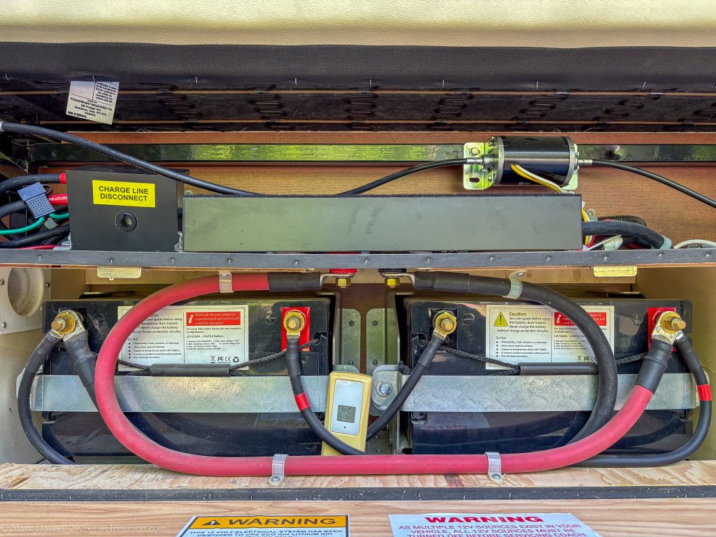
Before messing with wiring, we turned off the DC Power, disconnected the positive battery terminal at the house batteries, removed the fuse from the solar panel charge line and disconnected the output cables from the battery separator.
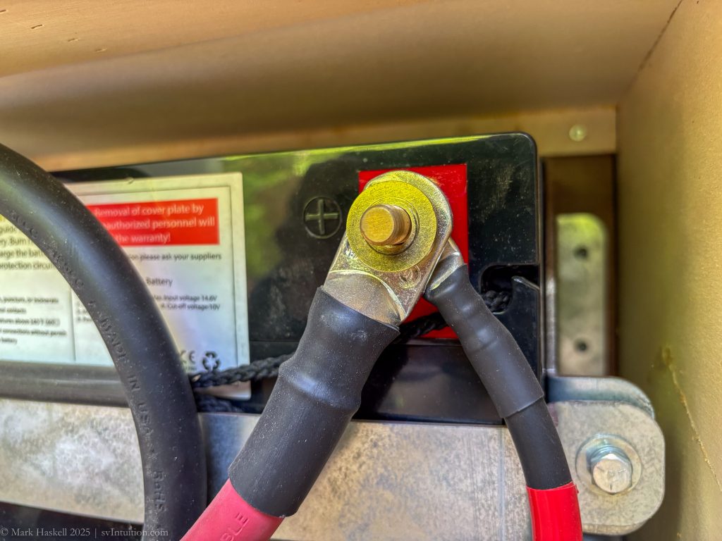
House battery (+) cable that feeds power to the house positive bus.
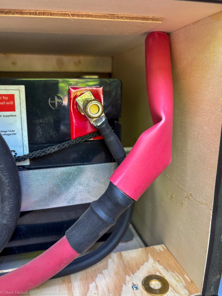
House (+) battery cable disconnected and covered with shrink tubing to insure there was no current while we worked on the system.
Fuse removed from the solar panel charge line.
Wiring the Charger
We did as much of this on a workbench as possible. Space is really tight when working under the couch.
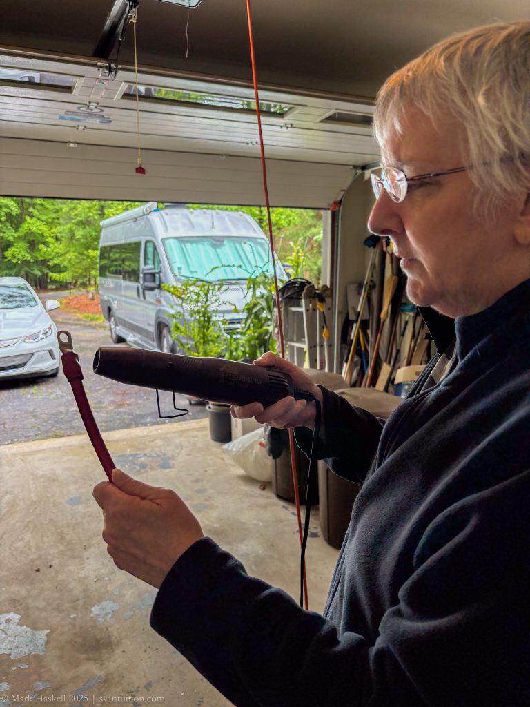
Beth sealing the heat shrink on a ring connector.
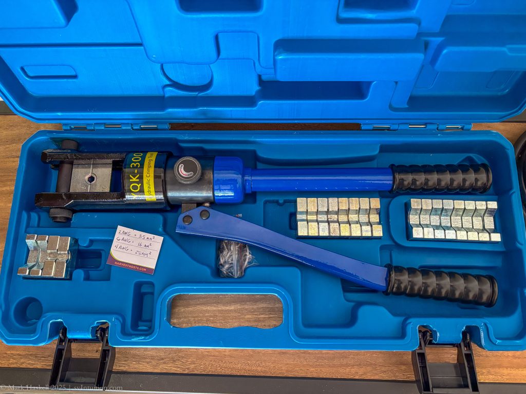
A pneumatic crimper makes the job much easier. Our next-door neighbor let us borrow this and it was perfect for the job.
Wire the power from under the hood to the input charge breaker
Scariest part of the whole project… Cut the wire
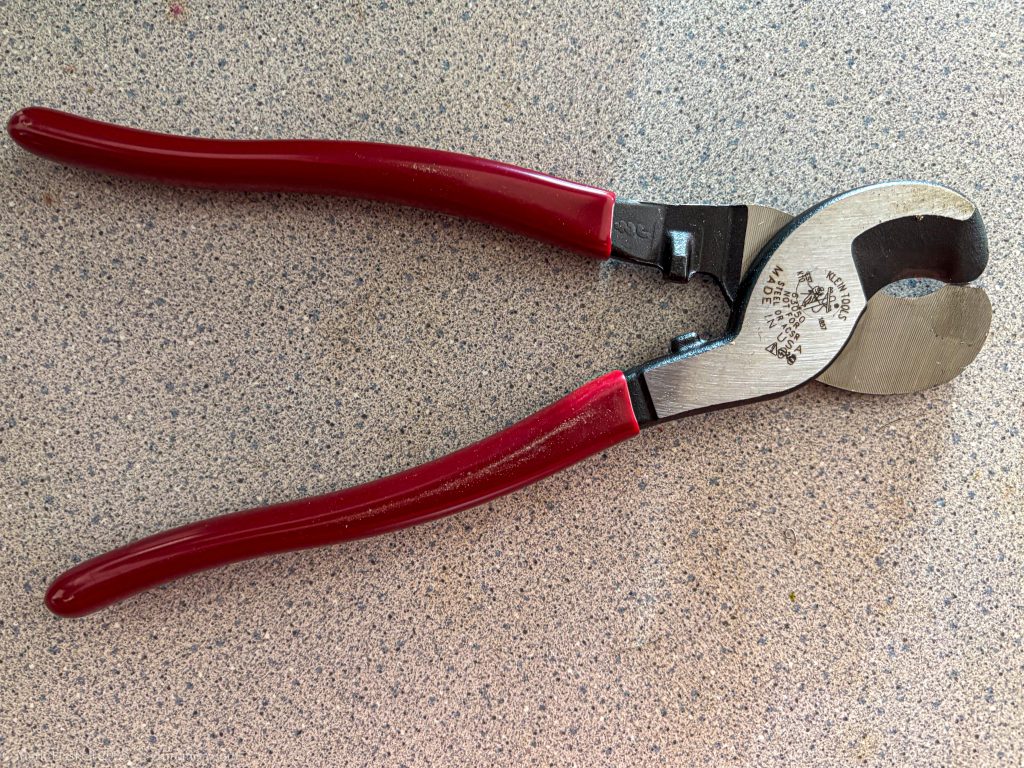
These are big wires and we’re working in limited space. These wire cutters made the job easier.
The Klein Tools Journeyman Cable Cutter J63050 is one recommended cutter.
Once cut, crimp a ring connector on the cut wire.
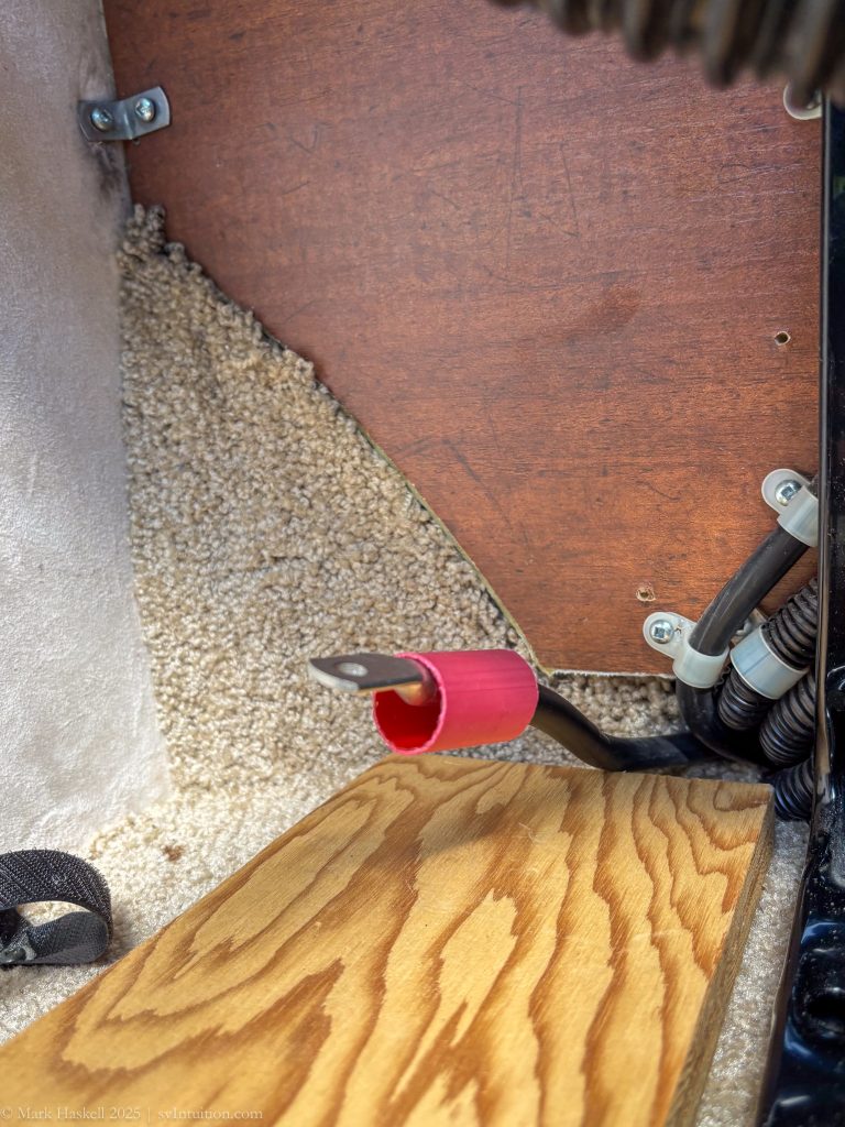
Add red heat shrink. This will protect the circuit and help identify the black wire as being positive (+).
Note: Pleasure-Way uses black wires for everything and identifies positive wires by wrapping them with red tape.
Here’s the wire connected to the input circuit breaker.
You can see that we removed the back couch cushion and the vent hose from the battery box to allow better access.
The input circuit breaker is screwed to the wooden panel under the couch.
There are three connections on the charger.
IN (+) Red from the input circuit breaker
GND (-) Black from the negative house battery bus
OUT (+) Red to the output circuit breaker
We fabricated three wires, each with a ring connector on one end and a heat shrinked, stripped connection on the other.
These are screw type connectors and only hold up to #6 (Check if #4) gauge wires. They are short, and haven’t become warm when charging.
A protective cover comes with the charger. We added heat shrink to each of the wires to help seal the wire openings.
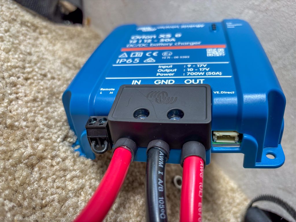
Another view of how the heat shrink and cover protects the wires.
Connect the Charger to the Input Breaker
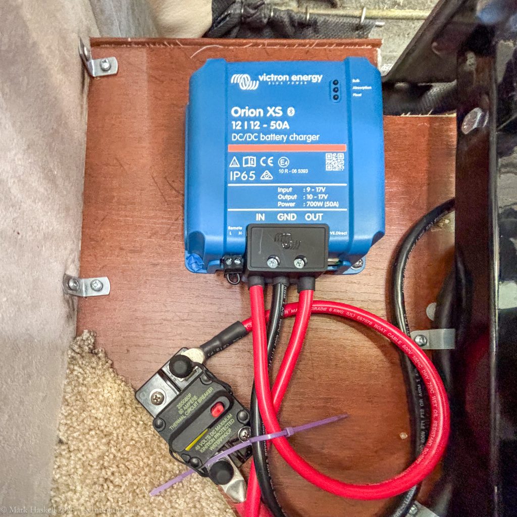
We mounted the charger to the wall above the circuit breaker. You can see the wire from the input circuit breaker to the charger.
Connect the charger to the Output breaker.
Zooming out, you can see the output circuit breaker mounted to the outside of the battery box.
Connect the Ground (-) Black wire to the negative battery bus (Add a photo)
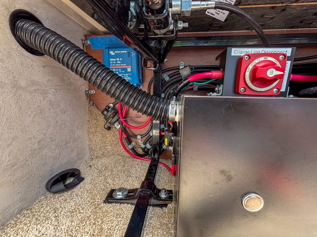
Connect the Output Breaker to the “Red Key” battery charge disconnect switch.
With all of this connected under the couch, we reconnected the (+) wires to the battery separator under the hood, reconnected the big red (+) wire in the battery box, and were ready to test the system.
Started the van and the Spyder control panel showed the batteries charging at 48 amps!
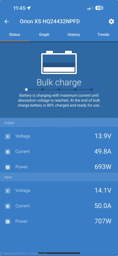
Connected the charger to my phone using the Victron app and we could see the voltages and amps flowing in real time.
Cleaned up the install by covering all the connection posts and neatly zip tying the new wires.
Still editing. More to come…
-> Add settings for charger
-> Add connection to charger ground
-> Add discussion of improved efficiency over the older 30 Amp Victron Charger
-> Add neighbor’s experience changing out 2 30A chargers for 2 50A chargers
Out with the Old
Once we had tested that the new charger worked, much of the wiring under the hood was no longer needed. We removed the two wires feeding the battery separator and the battery separator itself.
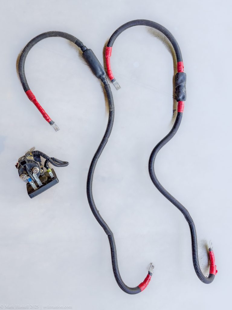
These two wires ran, in parallel, from the alternator connection at the chassis battery to the input of the battery separator. The red tape on each end indicates they are positive leads.
One of the output wires from the battery separator was connected to the fuse panel at the starter battery where the input to the battery separator had been connected. The other output wire was capped with heat shrink and zip tied to the back of the starter battery box in case it might be needed in the future. Note that these two wires run from under the hood to under the couch and are sealed with lots of silicone to keep insects or other creatures from getting inside the van.
Bonus: Replacing the “Red Key” Switch
While we were messing about with the wiring under the couch, we decided to go ahead and replace the Charge Line Disconnect switch as well.
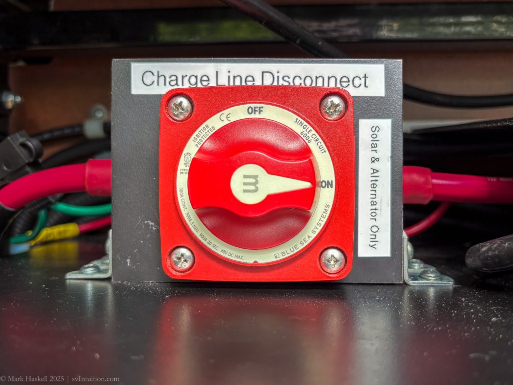
Details on how this was done will be added in the future. We used ideas from Rock Beaudet which he shared in the Pleasure-Way Owners Group on Facebook.
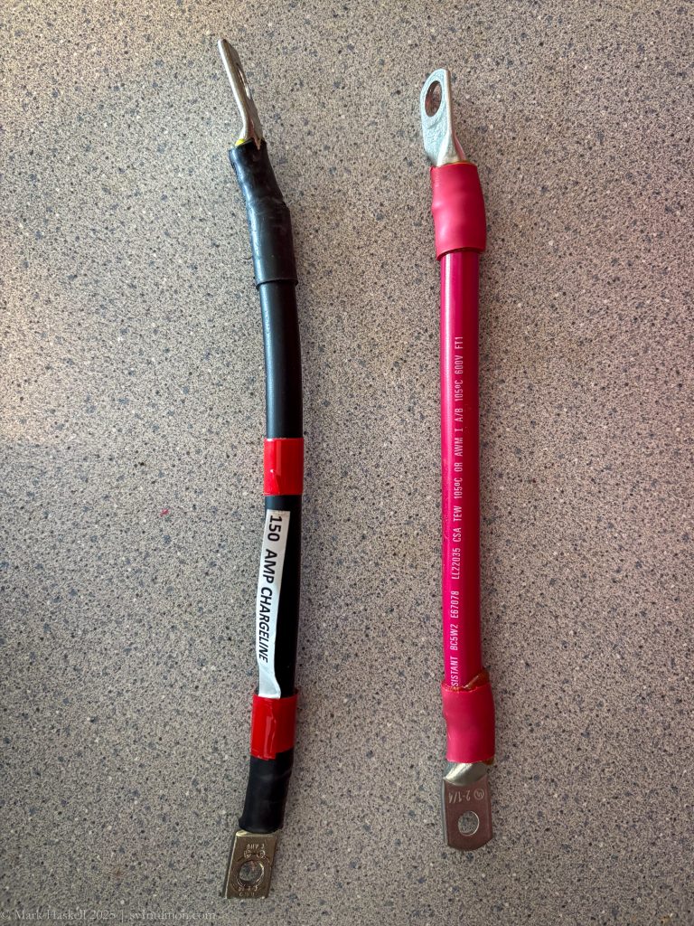
Made-up replacement wires from red boat cable we had saved from sailboat projects.
Leave a Reply